Do you understand piping and instrumentation diagram? What is it? If not, read this article and it will give you an overview of piping and instrumentation diagram.
Once understanding piping and instrumentation diagrams, engineers can read schematics and use them in identifying problems and know how to include them in reporting rig control problems.
Definition of Piping and Instrumentation Diagram
Piping and instrumentation diagram, also called P&ID, is a drawing in the process industry. It presents the interconnection of process equipment and the instrumentation which is used to control the process. And this kind of diagram is mainly used for laying out a process control installation.
And following are items that usually are found in a P&ID:
- Instrumentation and with unique tag identifiers
- Mechanical equipment with names and numbers
- All valves and their identifications
- Process piping, sizes and identification
- Vents, drains, special fittings, sampling lines, reducers, increasers, and swaggers
- Permanent start-up and flush lines
- Flow directions
- Interconnections references
- Control inputs and outputs, interlocks
- Interfaces for class changes
- Computer control system
- Identification of components and subsystems delivered by other
Here are also some items that are not included in a P&ID:
- Equipment rating or capacities
- Instrument root valves
- Control relays
- Manual switches and indicating lights
- Primary instrument tubing and valves
- Pressure temperature and flow data
- Elbows and similar standard fittings
- Extensive explanatory notes
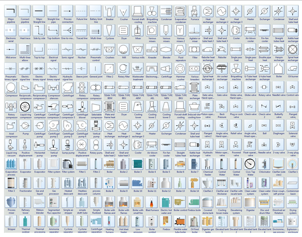
Common Used Symbols of P&ID
There are so many and various symbols used in piping and instrumentation diagrams. And all of them have their own usages. Symbols showed in the following picture shows are only the tip of iceberg.
Symbol Categories:
Basic Steps to Create P&ID
- Launch the piping design software and open a blank P&ID drawing page.
- Drag equipment shapes from Equipment on the left library and drop on the drawing page.
- Use pipelines to connect the equipment.
- Use the same way above to add valves and instruments.
- Rotate a shape until get the correct angle.
- Double click the P&ID symbols to add data.
Click How to Create Piping and Instrumentation Diagram to view detailed tutorial for creating P&ID.
Importance of P&ID
P&ID not only plays an vital role in maintaining and modifying the plant process after initial build, but also is important for enabling development of control and shutdown schemes, safety and regulatory requirements, start-up sequences and operational understandings. And as it is the last stage of process design, it also serves as a guide for people who is responsible for the final design and construction.
没有评论:
发表评论