UML deployment diagram is used by system engineers more and more frequently, but do you know how to create UML deployment diagram? If not, read this article!
This is an article which introduces UML deployment detailedly and gives you a step-by-step tutorial for creating it.
What is UML Deployment Diagram
UML Deployment diagram is a structure diagram which shows shows architecture of the system and models the physical deployment of artifacts on nodes. And the purposes of it are describing the hardware components used to deploy software components, visualizing hardware topology of a system and describing runtion processing nodes. Just take describing a website as an example, a UML deployment would show what hardware components exist, what software components run on each node, and how the different pieces are connected.
How to Create UML Deployment Diagram
Following are detailed steps to create UML deployment diagram.
- Launch the UML software and open a blank drawing page.
- Drag relevant UML symbols from left libraries and drop on the blank page, or click the floating buttons to add automatically.
- Double click the symbols and add the information.
- Connect UML symbols with correct arrows in order.
- Browse your computer and choose a location to save your diagram.
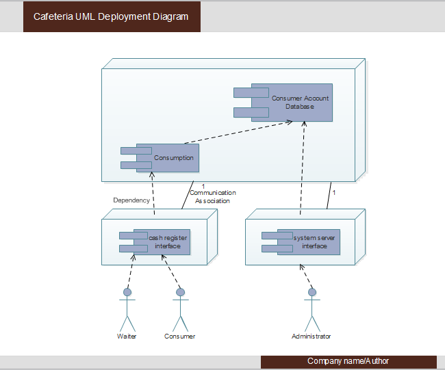
Here is the created UML deployment diagram example for you
Where to Use UML Deployment Diagram
The major usage of UML deployment diagrams used by system engineers is to describe the physical components or hardware’s distribution and association. We can also visualize UML deployment diagrams as hardware components or nodes where software components reside. Following are usages to which UML deployment diagrams are applied.
- To model the hardware topology of a system.
- To model embedded system.
- To model hardware details for a client/server system and a distributed application
- Forward and reverse engineering.
没有评论:
发表评论