Simple but effective guideline on how to create UML component diagram quickly.
This is an article which introduces UML component in detailed and gives you a step-by-step tutorial for creating it.
Definition of UML Component Diagram
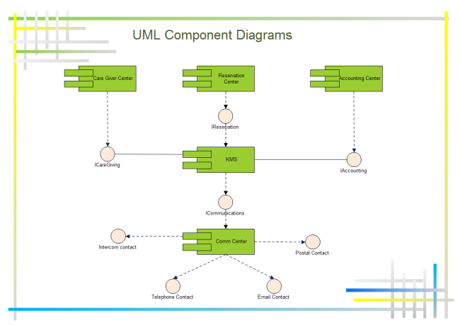
UML component diagram is a diagram describes how components are wired together to form larger components or software systems. It is often used to illustrate the pieces of software, embedded controllers and some other parts that make up a system and the structure of a it. The main purpose of UML component diagram is to show the structural relationships between the components of a system.
Steps to Create UML Component Diagram
Below is a step-by-step guide to create UML deployment diagram.
- Start the UML software you usually use, click Software, then double click UML model diagram to open a blank drawing page.
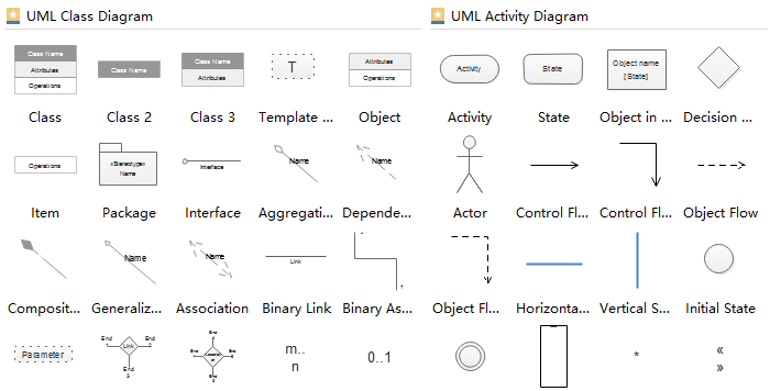
- Drag and drop relevant UML symbols from left libraries or click the floating buttons to add automatically.
- Double click the symbols and text the information.
- Drag proper connector from left libraries to connect symbols.
- Browse your computer and choose a location to save your UML component diagram.
Here is the created UML component diagram example for you
Ideal Software to Create UML Component Diagram
The UML Diagram Software i use frequently have got more and more popularity among people because of its following handy features.
A mass of standard UML component symbols for dragging and dropping. No requirement of drawing skills.
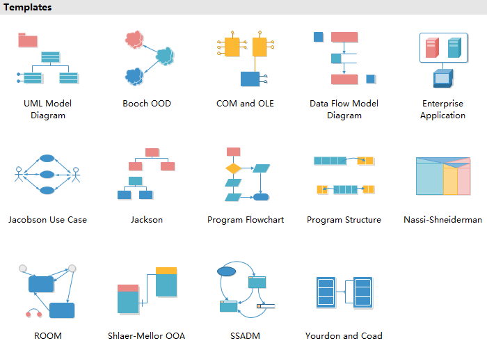
Abundant UML templates are offered for free downloading and customizing to meet different demands.
 Inserting resourceful data is supported by adding hyperlinks, note, and attachments.
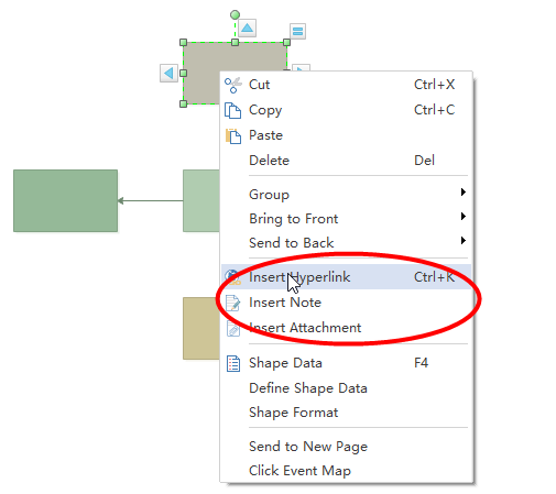
Usages of UML Component Diagrams
UML component diagram is a special type of UML diagrams which is used to visualize the static implementation view of a system and describe the organization of the components in a system. Software designers and developer usually use it to model the components of a system, database schema, executables of an application and system’s source code.
- To model the hardware topology of a system.
- To model embedded system.
- To model hardware details for a client/server system and a distributed application.
- Forward and reverse engineering.
没有评论:
发表评论